Boiler


2008 - 2020
                     
                                                   © John R. Bentley 2008-19.


               A miniature D-type industrial
Model Watertube Boiler

A back view of the tiny partially completed boiler

I felt, that with so many unfinished projects in my workshop far from completion, it would be nice to have a good general purpose miniature boiler to run a few steam engines for demonstration and experiment.  I have three finished engines on hand which are not connected to steam plants and it seems a shame not to be able to run them for guests - except on noisy compressed air.  The charm of a steam engine is totally lost when visitors are denied the pleasant smell of warm oil, feeling the heat and hearing the sound of the exhaust.  This boiler job provides a break from my Naphtha Launch Engine project which really has a lot of work yet to be done.


Please note:

  Pressure boilers which are improperly designed, constructed or operated can be dangerous regardless of their size.  
As I have stated elswhere, this is not a suggestion about how someone else should build a boiler but simply a description of how I made this particular example.


Of course the past year was the second year of the pandemic so let's hope that the virus will burn itself out in 2022 and we can all start having fun again. Here on our island 2020 was our hottest summer on record and wasn't great for working on the boiler or this website. Due to that I chose to spend more time with family and renewing old friendships (you might say my boiler and these web pages have been on the back burner recently). That carried on throughout 2021 and consequently the following pages have not been fully edited, just as the model is also not yet completed. There could be some inaccurate references, and typographical, gramatical or spelling errors. I hope to get back to my workshop and to more editing soon.  - John

Early mockups to give an idea of the general arrangement
(This is not a large model - the boiler only stands as tall as my hand)


(obviously the burner components were held together with clamps for these photos)


A later shot showing further work on the burner
(including temporary paint)


Test fitting a power supply module into one of the three electrical boxes on the burner front


This is not quite so serious as it might first appear :-)

The burner is intended to run without any electrical (or electronic) assistance. A tiny steam turbine blower will provide the necessary draft through the boiler as well as supplying secondary air for the methanol burner. However during starting, a battery powered electric motor will do that work until enough steam is raised for the turbine. As the motor, turbine and blower fan all share a common shaft, the motor will act as a micro power generator when the turbine is operating. I thought it would be nice to use an electronic voltage regulator to operate LED panel lights thereby indicating when it is safe to disconnect the battery supply from the motor after steaming up.


The pressure vessel in the final construction stages


I have embarked on a miniature D-boiler, modelled loosely after the large Cleaver-Brooks packaged industrial watertube boilers. This model will represent a typical CB D-series boiler circa mid-1970's. As a model it has much smaller drums than my original plan for a similar size Babcock boiler and hence materials for it are less problem to obtain.


D-type boiler is a term used particularly in North America which simply denotes a pressure vessel configuration which resembles a capital letter "D" when viewed from the end. Two small drums are located on the vertical line of the D - one at the top (the steam drum) and one on the bottom (mud drum).


- a quick note here:  the above and the two following images were taken from old Cleaver Brooks' publications and are used here under a fair use policy only to demonstrate the direction I am following in this hobby project. I will not do battle with anyone representing the company on this matter and will willingly either give further credit or make these images disappear from my page on their request.


In order to work safely and efficiently, the number of tubes must be reduced greatly and the diameters increased.  The only way a small, exact scale model of this pressure vessel could work is if the water and the hot gases could be scaled as well.   Perhaps if liquid nitrogen were used in the vessel which seems much "thinner" than water, and heated with warm helium gas (instead of fire) it might work!  Anyway I'm using water and a flame so I must capitulate to the demands of physics.

In operation: the fire is projected longitudinally through the open space of the D, which is enclosed by walls of water-filled tubes. These tubes receive heat by radiation from the flame. When the hot combustion gases reach the back end of the boiler, they are turned around 180 degrees and come forward between a bank of vertical water tubes (convection bank) which extract heat by contact with the gases as they pass toward a large flue gas outlet at the front of the side wall leading to the smokestack. This convection bank is represented by the thick vertical line on the left side of the capital letter "D". Typically as much as 70% of the heat is transferred to the water in the open section of a D boiler and the remaining 30% of the heat transfer takes place on the return pass through the convection bank. It is a popular type of boiler both on land and formerly in oil-fired warships.


The Cleaver Brooks brochure illustration below depicts a typical D-type boiler in their range.  This illustration shows the boiler with the CN version of the burner/windbox installed, I will copy the BR burner for my model which has a slightly different appearance.
 
 
The proportions varied considerably depending on the output capacity of the various prototypes.  I plan to fit the largest upper drum possible into the scale casing, to ensure a reasonable steam reserve capability.  I also am using very much fewer (and larger) tubes to get fast heating and good circulation without any steam locks in the tubes.  I expect to strip much the detail shown in this drawing from my model, but I will use the general shape as the pattern for my boiler.

Of course my boiler will require fittings, but they will be larger and different from those above out of practical and safety considerations. 
 
 
These drawings are typical examples of an average-length "D" boiler from CB's range
 
 
My model will be a right hand boiler (as shown in the left drawing).


My plan is to use this model as a small shop boiler to run a few of my loose engines and to test any new ones that I may make. A watertube boiler is not always the best for the shop as it requires paying close attention to water and firing levels much more diligently than a pot boiler. However a watertube type raises steam very quickly and is faster to shut down - well suited to the requirements of quick testing in the workshop.


Construction:

Note:
I am adding comments and pictures as I work along in this project. Some of the text here (and in pages to come) may appear to suggest that the "present" covers a very long span of time which started some weeks, months or even years ago.  Please remember also that in many cases the "future" as referred to in these pages has already come and gone!


The fabricated bottom skid of the boiler awaiting cutouts for the mud drum


The girders are made from standard window curtain rod (for travelling curtains)


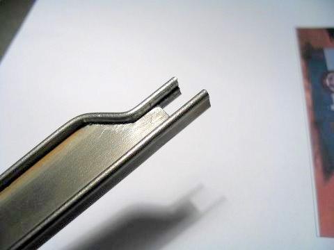
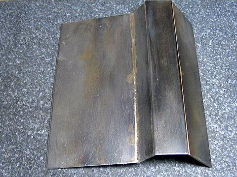
End flanges partially formed


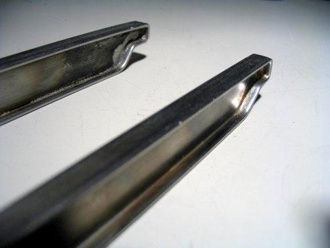
Two ends finished and silver brazed


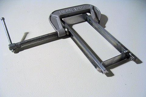
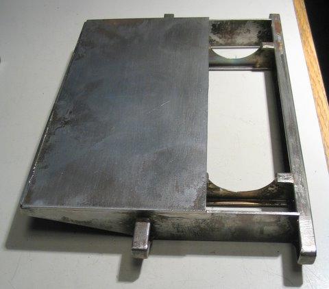
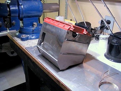
Beginning the assembly of the skid


Lots of clean-up and silver brazing yet to do


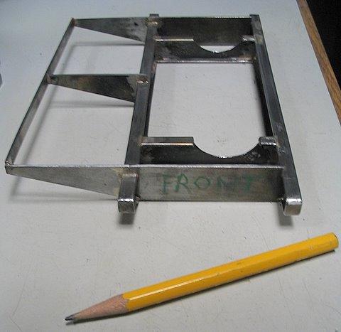
A dull pencil is a sign that lots of work has been going on!


(those are not "rusty spots" but some sporadic copper plating that happened in the pickle solution)


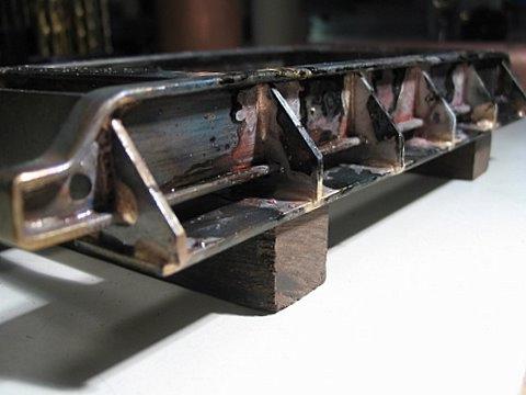
Convection-section floor with the supporting gusset piece awaiting brazing


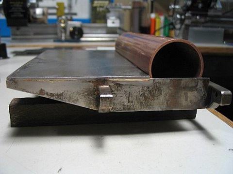
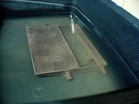
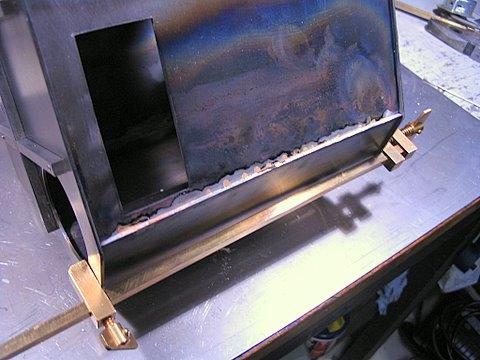
The mud drum shell being tested in its eventual position


Cooling off - upside down after silver brazing


Back into the acid!


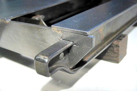
Painted in red oxide...the mud drum cradle is visible here


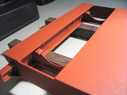
Note the minimum amount thermal contact surface area between cradle and drum.  I am making every attempt to prevent heat loss from the drums and tubes. I intend to totally eliminate any metal-to-metal contact between the boiler and its casing.  The casing will be well insulated with Cerrablanket material.


The finished skid on the bench awaiting flat black paint


Fitting the front (inside) corner of the casing wall-retainers
(not yet screwed down)


Completed wall retainers
(bolts yet to be cut off flush)


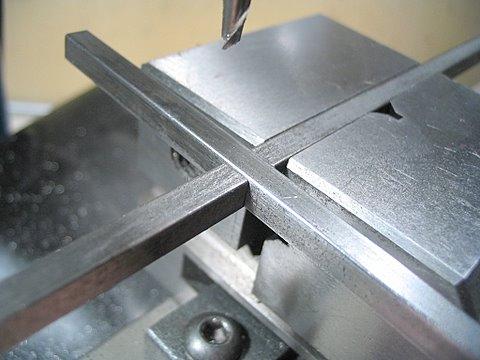
Cutting the cheeks to create cross lap joints in the front plate stiffening bars


Checking the cross lap joint fit


Front plate mocked-up


Stack material will be made from this piece of thinwall steel electrical conduit


Checking casing wall retainer height for parallelism on a granite surface plate
(prior to silver brazing the steel angle to the boiler casing's front plate)
 
 
The retainers are only screwed (not brazed) to the skid and will be easily removable


A small length of the retainer silver-brazed to plate


Dremel disk (black circle) cutting through after chain-drilling for steam drum opening
( - those are sparks, not scratches to the left! )


The end of a dirty job!


Same opening after filing smooth
 
 
(this opening will be covered by a round plate, leaving an identical-sized hole to the lower drum access hole)


Just 3 more sides, 4 roof sections, a burner unit and the pressure vessel to go!


Note that the bottom of the lower drum access hole
 has been cut into the red oxide skid assembly, as per the prototype
 
 
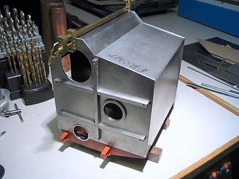
The opening on the right is the burner firehole
 
 
The rectangular boiler flue gas outlet is marked out on the side wall


Flue outlet cut out - yet to have the stack duct attaching flange added


This is hard to understand from pictures:
 
The front and back plates lap over the skid, while the side walls simply butt against the floor of the skid. There is a reason - inside access for inspection will be provided by lifting the complete roof and side walls in one piece upward from between the front and back plates. Note there is a small reveal of those plate's edges past the side walls..
 
 
As the project progresses a matching base trim strip at the bottom of all walls and thin batons reinforcing the side walls will be added to resemble the prototype. Actually the prototypes use small T-bars on the sides, but in proper scale they would be very fragile for a working unit of this size.


Inside retainer strip keeps the wall (and ceiling eventually) from going in too far
(The main purpose is to provide a seal against air leaks
into the enclosure which would destroy the draft)


Starting fabrication of the roof


My plan is to edge-braze the pieces with Easy-flo 45


Yeah, ok - I got away with it...


Better than expected


The shed roof section on the right will be silver brazed in situ


(the shed roof piece on the right actually overhangs the wall - that's a pencil line on the roof, not the top edge of the right wall)


Checking that the four corners are in one plane on a granite surface block


Now it's time to join walls and roof (along the white seam)


Chopin' up some silver brazing alloy
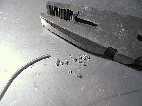


Ready to go


 After the heating


Easy-flo 45 has flashed into the joint beautifully -
Hooray for propane gas and a four-dollar torch!


These last shots show how the boiler casing looked as of Dec 16, 2008.
 
 
There is still quite a bit of cleanup and trim work to be completed...also a couple more openings at the back and flanges to be fitted. The entire inside surface of the enclosure will be lined with shiny aluminum tape, covered by a one-half-inch layer of high temperature thermal blanket insulation. There are holes needed for various connections to the upper steam drum (upper one) - such as water gauge glass, pressure gauge, feedwater inlet, blowdown outlet and on the top - two safety valves, a main steam outlet, vent valve etc..
 
You can see how the unit will open for the installation of the pressure vessel assembly


I suspect the boiler housing will be painted with flat black "barbeque grill paint" along with the stack.  The original Cleaver Brooks boilers of this vintage were painted a nice metallic blue which I like, but maybe that is a bit too "cutesy" to couple to 19th century steam engines.  I'm thinking that the dull black with a bit of copper and brass pipework will go with anything - old or new.  Boring it may be, but the point is to show the off engines.
 
 
Those piers are temporary and will be replaced with shorter versions equal to the distance across the two skids
 
In the end I hope that the boiler and stack will stand proudly on a simple base, which may contain a water replenishing tank.  Probably there will be a pump and fuel tank above ground on the same base.  The burner / windbox assembly is very large and will stand vertically in front of the firehole.
 
The copper pressure vessel components will be started in the New Year (2009) after I have time for a good clear run at them.   I am looking for a 1/2" phosphor bronze rod to make the threaded bushes for the drum.  People in my area tend to throw up their hands and say "what is phosphor bronze?"  Gunmetal which is also suitable for this purpose is unheard of in North America.

There is Commercial Bronze - no good, as it contains too much zinc, there are machining bronzes which contain lead, but Phosphor Bronze A, B or C are almost "pure bronze" - copper and tin.  They will not disintegrate in a model boiler like many of the brassy bronzes.
 
 
You are on Part 1

Part 2 (drums)


or


Return to ModelEngines.info homepage