John R. Bentley 2009.
2008 - 2009.
John R. Bentley 2009.
Model Watertube Boiler
- A miniature industrial D-type boiler -
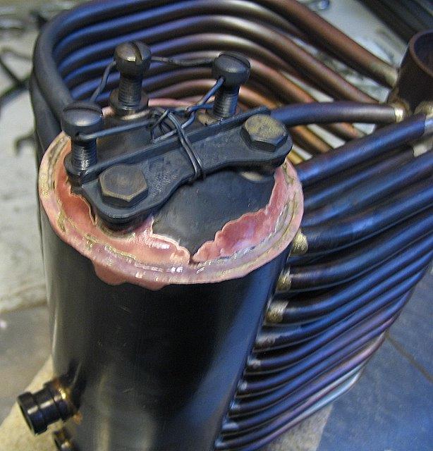
Immediately after brazing the front head(sorry about the camera jitter - that thing was still searing hotand the radiant heat on the camera and my face was tremendous!)Silver brazing - isn't it beautiful!ACID ROCKS!I just use ordinary citric acid because...
1. it doesn't burn my clothes
2. it is reasonably safe in most respects
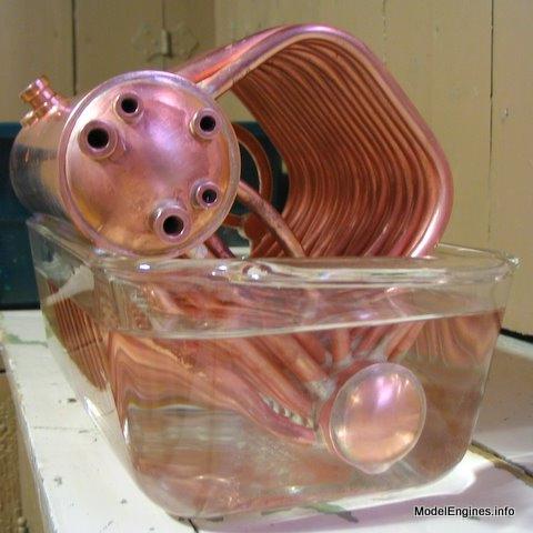
3. it is also gentle - but I can easily spice it up by heating it.On March 26 2009 this boiler passed a milestoneThe hydrostatic test was conducted on the pressure vessel assembly Thursday night (Mar 26). It was filled with water at 240 psi (16 bar) of pressure and held it at that level for the recommended 30 minutes. This is double the designed maximum working pressure (in this case 120 psi) as a proper test for copper boilers requires. In practice, I usually run steam only at 60 psi for most of my models, but want to be able to safely use more for operating expansion engines.'Nary a drop of water escaped from any of the 139 silver brazed joints - nor did anything deform. It looked every bit as benign under that pressure as it does right now, sitting on the desk in front of me - dry as a bone with all of the ten threaded plugs removed.Now I will be able to turn my attention to the marriage of the boiler enclosure and pressure vessel, with thoughts of the burner, stack and tanks not far down the road.They say a picture's worth a thousand words ...The boiler is 100 percent full of water in this viewAt last it is now safe to clean off all that red and black firescale :-)By standing it on end, if any drop of water should leak out, it will travel down and be visible on the stainless steel sheet under the boiler...You can see how much leaked:NONE - not a single drop in thirty minutes.
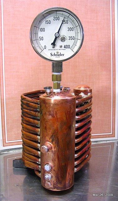
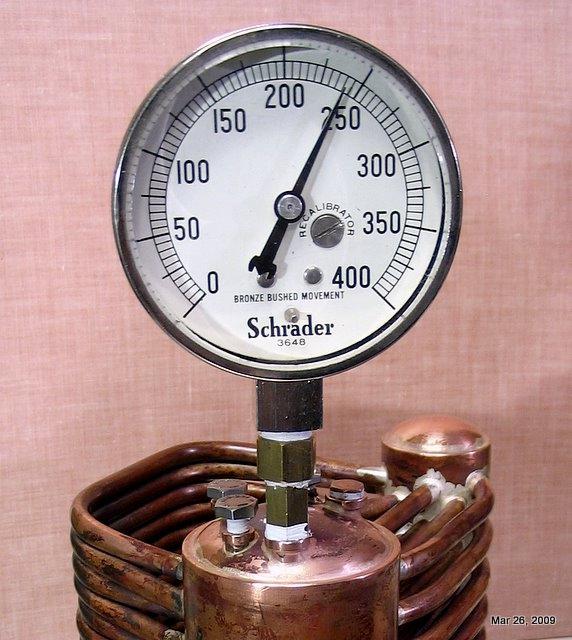
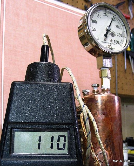
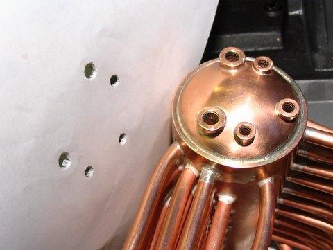
(the boiler is still under full 240 psi pressure in this shot)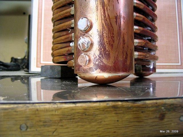 Here is a close-up showing the vessel being tested to 240 psi (1,654 kPa)110 F (43.3 C)
In this case the temperature required for the test was quite low- not enough to obscure the evidence of leaks by evaporation
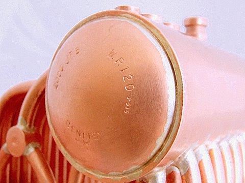
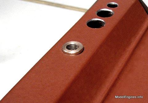
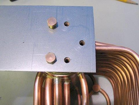
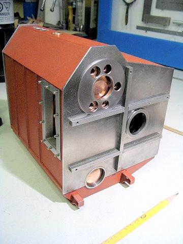
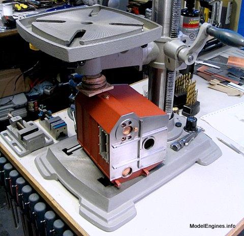
Stamped for maximum working pressure of 120 PSIThe steam pressure vessel in front of my computer monitor- it is now ready for mounting in the steel enclosure
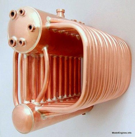
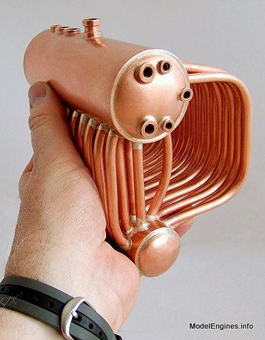
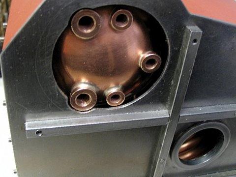
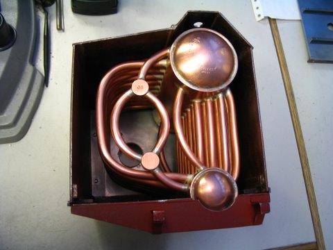
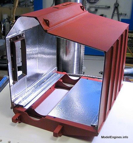
(Yes - I have two widescreen monitors here as well, but it is not a very useful format for most pictures)Ready for the installation of baffle plates to direct the hot gases
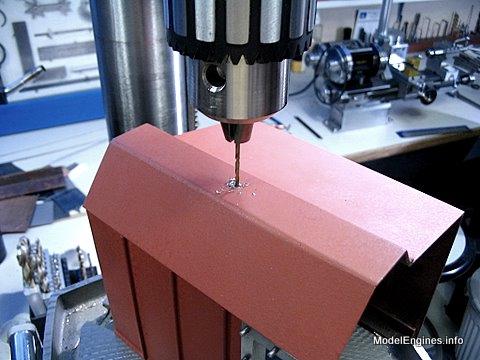
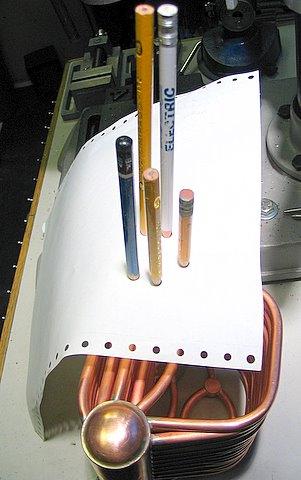
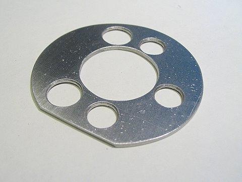
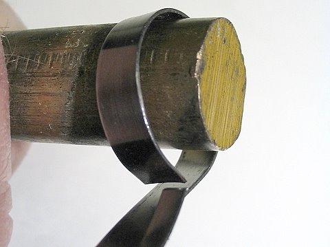
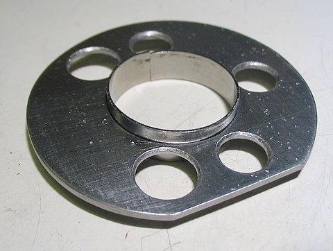
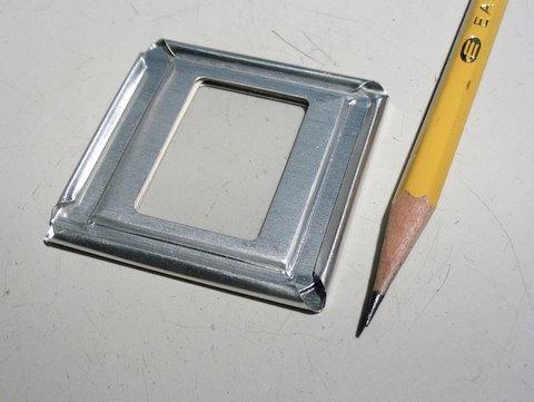
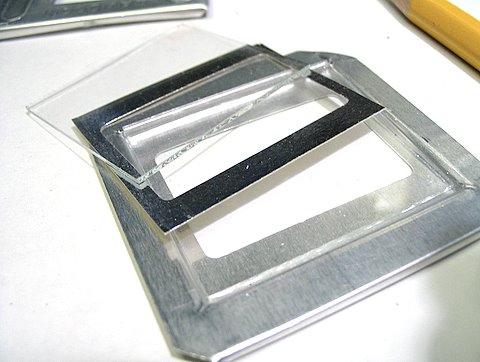
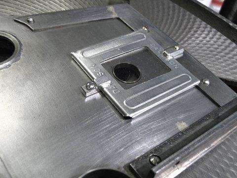
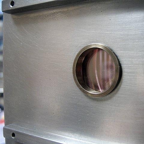
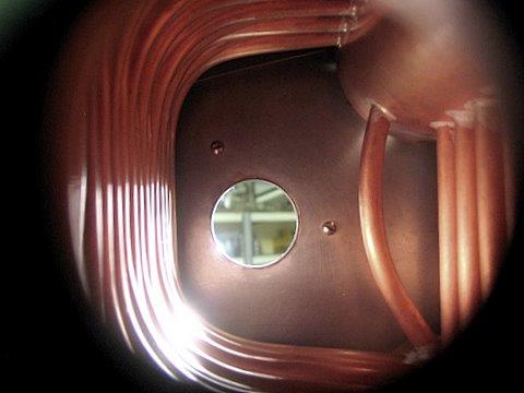
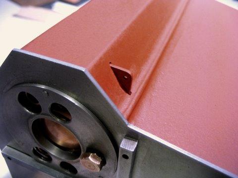
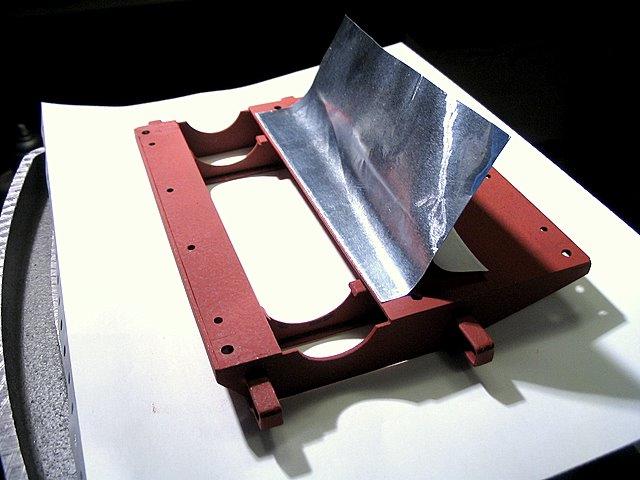
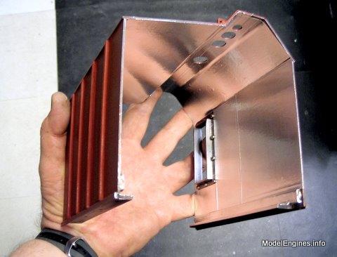
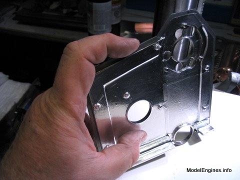
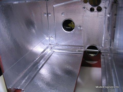
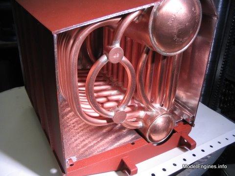
It is not easy to see from these photos that there areactually four rows of tubes in the convection sectionBeginning the marriage of the pressure vessel and boiler casingDrilling for steam nozzle, safety valves and the vent valveThe lower portions of the safety valve bodies will be under the roof(for a better scale appearance)Next problem: to make a coverplate to match the front gauge and pipe connectionsWhy use one pencil when five will do!The pencils are stuck in each of the ferrules to create a paper templateI knew that ancient pile of fanfold printer paper would come in handy some day...Copied on to sheet steel and drilledCut out(but not yet cleaned up!)Bending a piece of old packaging strap to make a hole linerTest fitting - it is ready for brazingPrepared to mount the plate with stainless screws from the insideInside view with back removed showing cooling tube loop for the furnace viewing portDavidson aluminum 35 mm slide framean easily replaceable solution for the view port glazingThe two glass sheets are each less than 1mm thickthe foil-covered paper mask leaves a tiny insulating air spaceTwo simple clips hold it in placethe insulating blanket will cover all but the round portholeA 12L14 steel ring in the back plate completes the jobOn the outside looking forward toward the burner firehole in the front plate(insulating blanket will also cover the inside of the front plate)I knew that drill press table was good for more than just drilling!(put to good use in holding the pressure vessel down inside its casing via twoblanking plugs screwed into the safety valve holes on the drum top)The objective was to hold two cork protectors between the bottom drumand the cradle while a high temperature adhesive set.Hoisting lugs have been added at the balance pointAdding the heat-reflecting aluminumBetter than black steel sheetNote the top of the flue gas outlet frame is contoured to clear upper drumA lot of tricky things to get around on the front plate(and the back was a more difficult job with the glass slide)I think it will reflect heat alright!Silvering completed.(note the right hand wall is not fully seated in this posed shot)Waiting to attach the Cerablanket and rigid Cerrafelt
You are on Part 6